Thursday, October 30, 2014

Purchase Fiber Adapter Panels

Because the laser light is dangerous, and the ends of every fiber optic cable(have a small core) must be encased in some kind of enclosure. So, the enclosure not only protects humans from laser light but also protects the fiber from damage. Fiber wall plates and fiber patch panels are two main types of fiber enclosures. Previously articles have been discussed how to use a fiber optic patch panel. Now we'll learn about under what situation it can be used and where to buy.
As previously mentioned, fiber optic cables have a very small core that can be easily damaged if not protected properly. Also, to be consistent with the minimum size of a fiber optic loop and not violate the critical angle, we need to have a way to keep excess fiber optic patch cables, as well as terminated building fiber, neat and protected from damage. Fiber optic wall plates and patch panels allow the cable installer to protect the delicate fiber cable from damage, while still making it useable for the network administrator.
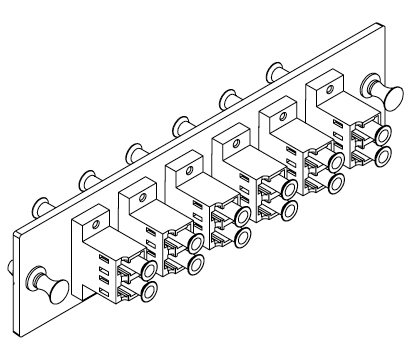
A common device that is used as a fiber optic cable enclosure is called a Lightguide Interconnection Unit(LIU), as showed in Figure 1. The LIU provides a location to terminate individual fiber optic strands into a patch panel, which will be discussed in the next article. A LIU is generally made of galvanized steel that is then powder-coated to provide durability. Most major LIU manufacturers make their devices 19 inches wide so they can be installed in a normal communications rack, If the LIU is to be located in an environment where there is a risk of moisture or corrosives, the LIU can be sealed with gaskets to make it virtually waterproof. Most LIUs have swing out trays in the front and the back to provide easy access to the patch panel to ensure that all loops are a minimum diameter, so the cable will not get damaged and maximum light can traverse the cable.
LIU500x500
Figure 1. Lightguide Interconnection Unit(LIU)
Patch panels for fiber optic cables also called fiber patch panels, which are usually installed into the LIU. Because the core and cladding of two fiber optic cables that are to be joined together must match perfectly, the fiber patch panel must be manufactured to exact specifications and some standard type connector must be used to ensure a good fit. (fiber option connectors are discussed in the next section.) Another fiber patch panel issue deals with attenuation. Remember from the previous article discussed that when you splice or join a fiber optic cable, you can introduce additional light loss or attenuation. The same holds true for the fiber optic patch panel. The connectors on the patch panel should identify the total loss at various wavelengths, and these losses should be added to any other cable loss on that particular cable to ensure compliance with standard and good operation of the fiber optic cable. Figure 2 is a LC adapter panels (6 port fiber patch panel) .
lc_fiber_optic_adapter_panel_6_duplex
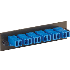
Figure 2. LC fiber optic adapter panels
Fiber Adapter Panel (FAP) is used for patching a fiber cable to the enclosures like fiber wall cabinets, rack mounts fiber cabinets or rack mount fiber shelf. It allows you to make quick and easy fiber patch panel connections as they can snap into the fiber optic enclosures easily. Fiber adapter panels are designed to fit fiber optic blank patch panels, rack and wall mount enclosures. To purchase this kind of fiber adapter panels, please visit Fiberstore’s website (www.fiberstore.com).
Learn more about fiber patch panels:

Tuesday, October 28, 2014

The Importance of Fiber Patch Panels

Fiber patch panels are a key and frequently overlooked component of any fiber optic network. Essentially, fiber patch panel serves as a network's central location for monitoring and connecting circuits. Frequently, they serve to connect and disconnect fiber optics equipment. Picture a panel as a traffic signal, it's the traffic signal that monitors and controls the flow of traffic through its intersection. A fiber patch panel is an absolutely critical component for uptime, performance, speed and other important characteristics.
Fiber Adapter Panel
Importance of fiber patch panels
Available in different sizes and configurations, Fiber patch panel can be tailored to match your fiber optic network's unique needs. But all fiber patch panel is similar in one regard is that they're important for any fiber optic network's ability to configure new equipment and also phase out old components. Fiber patch panels are versatile enough to manage fiber optic cable networks. More and more people recognize the value of fiber patch panels. Lots of network engineers believe that fiber's gaining speed and ability to easily upgrade existing networks. One thing's for certain is that no network can run well without a properly configured fiber patch panels.
Also referred to as Jack fields and patch bays, fiber patch panels consist of ports to quickly connect fiber optic cables. Fiber optic patch cords are employed to data streams entering and exiting the fiber patch panel. While no physical limit exists for a fiber patch panel's size, most have anywhere from around 6 to 96 ports. For larger networks, hundreds of ports can be utilized. That is another element in a patch panel's importance is that as your fiber optic network grows, ports can be in addition to accommodate ever-expanding demand. Fiber cable management is another important aspect for any properly configured network. Fiber patch panels also assist electricians and network engineers by offering convenient, flexible routing options. Because a patch panel has numerous ports in close proximity, fiber optic cables can be routed, labeled and monitored easily and efficiently.
Where to Buy
As the most important part of fiber patch panels, the importance of fiber adapter panels cans be imagined. Now that you've already know a lot about fiber patch panels, you can see the importance of having fiber adapter panels in place. Fiberstore offers an impressive assortment of patch panels to help your network to achieve optimum performance. Fiber optical patch panel supports the distribution, termination and storage of fiber optic cables. Fiberstore supplies various of brand fiber adapter panels including Black Box, Wirewerks, Mr-technologies, Corning, Leviton, Panduit Opticom adapter panel and more. By the same time providing all industry-standard coupler interface including LC, SC, ST, FC, MT-RJ, MPO and etc.What's more, we also can provide wall mounted type fiber patch panels. Additional information, you could view our website www.fiberstore.com.
Related Posts:

Introduction of Fiber Adapter Panels

As we all know, fiber optic adapter is a device used to connect two fiber optic connectors in the fiber optic cabling system. Due to the variety of fiber connectors, there are also a variety of fiber optic adapters (Read more about adapters here!). Why we talk about fiber optic adapter in the beginning of this paper? OK, because today’s main topic is related to the fiber optic adapters – the fiber adapter panels (FAPs).
What is Fiber Adapter Panel
Fiber adapter panel is a panel used for patching fiber cable to the termination enclosure, such as fiber wall cabinets, rack mount fiber cabinets or rack mount fiber shelf. Due to its convenient design, it can easily and quickly snap into the front of fiber optic patch panels or enclosure. It is a good option for easy network deployment or moves, adds, and changes.
6112DLC__21933.1408405965.500.500
Types of Fiber Adapter Panel
According to the connection types, such as LC, SC, ST, FC, MT-RJ, MPO etc., there are many kinds of fiber adapter panels. In addition, unloaded and blanks design are also used in some applications. Certainly, you can choose simplex or duplex type according to your demands. Moreover, number of fiber and the pack are another options designed in the fiber adapter panel. Nowadays, the well known brands of fiber adapter panel is Panduit, Blackbox, Corining, Wirewerks etc.
fiberstore-adapter-plates-fs
Application
Fiber adapter panel provides a complete system solution for connectivity, such as horizontal and vertical MPO adapters, LC, Keyed LC, SC, ST, FC, MT-RJ, E-2000 and fiber optic adapter modules, copper jack modules and audio/video modules. With its specialized design, it is best suited for installing in rack and wall mount enclosures and fiber adapter patch panels. In addition, it leaves some futher application spaces for the customer. For example, multimedia modular panels allow customization for installation requiring integration of fiber optic and copper cables. Blank fiber adapter panels reserve panel space for future use.
High-Density-Slide-Out-Patch-Panel-Rack-Mount-1RU-3-Adapter-Panel-2-Splice-Tray-Capacity
Where To Buy
In order to make network deployment and Fiber Adapter Patch Panels moves, adds, and changes more easy, fiber adapter panel is more and more widely used with people in the network solution. Where to buy highly quality fiber adapter patch panel with a low cost may be a concerned question of many users. Fiberstore offers a low cost option of fiber adapter panel for you. We have a variety of customizable options which are available to fit all your applications. Additionally, our compatible fiber adapter panel are fully compatible with the major brands, such as Black Box, Wirewerks, Mr-technologies, Corning, Leviton, Panduit which supply a good and low cost product choice for you.
Related Articles: http://www.fiber-optic-transceiver-module.com/introduction-of-fiber-adapter-panelsfaps.html

Monday, October 27, 2014

The Conventional Fiber Adapter Plates Need To Improve

Optical fiber has been used as a medium for telecommunication as well as networking because it's flexible enough and could be bundled as cables. Optical fiber has been especially advantageous for long-distance communications because light propagates through the fiber with little attenuation compared to electrical signals carried by conventional wire cables. Over short distances, for instance networking within a building, optical fiber interconnect cables save space in cable ducts because a single fiber can carry more data than a single electrical cable.
Interconnect cables are generally used as intra-equipment jumpers or patch cords. For example, some typical applications include patching active electronics to nearby patch panels, cable cross-connection on distribution frames, and connecting work area outlets to terminal equipment. Fiber optic patch cords comprise a length of cable with a plug or connector on one, or both ends, and can also be referred to as connectorized fiber optic cables. A patch panel typically comprises a connecting hardware system (e.g., racks, adapter plates, arrays of adapters, etc.) that facilitates cable termination and cabling administration via the use and administration of standard-conforming adapters. The following figure is a 12 port fiber patch panel, which is a component of fiber cable installation
Benefit From Fiber Patch Panels
Various fiber optic cable connector and adapter designs can be used to meet the requirements of corresponding Fiber Optic Connector Intermateability Standard (FOCIS) documents. Note that the term adapter, when used in reference with optical fiber, has been defined by the optical fiber industry and standards organizations as a mechanical termination device designed to align and join two like optical connectors.
In some designs, fiber adapter plates provide the means to support and align the interconnection of connectorized fiber optic cables in structured voice or data cabling networks. Conventionally, fiber adapter plates use a metal or plastic plate or support panel having a number of cutouts to accept discrete fiber optic adapters which are typically linked to the adapter plate by screws or clips. Therefore, these adapter plates use a removable attaching mechanism (e.g., screws, clips, latches, etc.) to attach the adapter plate to an enclosure or patch panel.
However, such conventional adapter plates suffer from drawbacks due to the assembly of so many discrete parts. For example, alignment of the connecting optical fibers is crucial to minimize loss across the adapter. While internal fiber optical interface details (e.g., alignment, cable separation, etc.) are specified by rigid standards, the adapter to adapter plate connection is more springy. As a result, excessive tolerances can result in additional mechanical play between the adapter and the adapter plate which can, sometimes, to enable excessive stresses and bend radii of the connecting fiber optic cables.
As a further example, such conventional assemblies by their nature require costly assembly steps. As a cost saving measure, some of the assembly steps can be passed on to the end user. However, this can lead to increasing set up time, having costs of its own, and can result in end user frustration. Furthermore, conventional adapter plate panels are often unlabeled or stamped with labels that are hard for the end user to ascertain, specially when the adapter plate is fully outfitted with adapters and cabling.
It is thus desired to provide fiber adapter plates that improve upon these and other deficiencies of conventional fiber adapter plates.
Fiber Adapter Panels Privided By Fiberstore, loaded with LC, SC, ST, FC, MT-RJ, MPO and unloaded blanks. With products compatible for trusted brands including Black Box, Wirewerks, Mr-technologies, Corning, Leviton, Panduit Opticom adapter pannel and more.

Wednesday, October 22, 2014

Fiber Adapter Panels Privided By Fiberstore

When surmounting trouble rises, a fiber optic technician must choose the most suitable patch panel for a specific situation. He has to understand that when it comes to easy installation, proper termination and long-term maintenance, its not all patch panel is made equally.

Optical fiber is robust and thus deserves some kind of special treatment. For example, if your horizontal copper cable is broken, one user is about be affected. If your backbone fiber goes down, it will grab a lot of users down by using it. For this reason using fully enclosed connecting hardware for optical fiber is essential. This is where the technician must choose between using wall-mounted or rack-mounted hardware. The optical fiber density required will likely influence the technicians choice between the wall-mounted and rack-mounted connectivity. Many technicians will choose to use fiber patch cables. However, how to handle the fiber patch cables?

What is Fiber Adapter Panel?

Fiber Adapter Panel (FAP) is utilized for patching the fiber cable to the enclosures like fiber wall cabinets, rack mounts fiber cabinets or rack mount fiber shelf. It enables you to make fast and simple fiber patch panel connections as they can snap into the fiber optic enclosures easily.

OM3/4 10G Duplex Plastic Adapter Plate

Fiber Adapter Panel provided by Fiberstore:

  • Loaded with LC, SC, ST, FC, MT-RJ, MPO and unloaded blanks
  • Simplex and duplex (6-pack or 8-pack)
  • Metal or Cerramic sleeves
  • Ideal for 6-fibers, 8-fibers, 12-fibers or 24-fibers, 48-fiber, 72-fibers and 96-fibers applications
  • Snap quickly into the front of our compatible fiber optic enclosures

Fiber adapter panels contain TIA/EIA-604 FOCIS compliant or compatible simplex or duplex fiber optic adapters and meet or exceed TIA/EIA-568-C.3 requirements. Fiber adapter panels include horizontal and vertical MPO adapters, LC, keyed LC, SC, ST, FC, MT-RJ or E-2000 fiber optic adapters. Fiber optic adapters include phosphor bronze or zirconia ceramic split sleeves to fit specific network requirements. LC and SC adapter housing colors follow the TIA/EIA-568-C.3 suggested color identification scheme.

Multimedia modular panels allow customization of installation for applications requiring integration of fiber optic and copper cables. Blank fiber adapter panels reserve fiber adapter panel space for future use. All fiber adapter panels snap quickly into the front of fiber optic patch panels and enclosures for easy network deployment or moves, adds, and changes.

Fiberstore's fiber adapter panel with metal or plastic is meant to be used for patching the fiber cable to the termination enclosure of your choice, such as fiber wall cabinets, rackmount fiber cabinets or rackmount fiber shelf (LC patch panel). The adapter panels are easily snapped into the enclosures with snap lock mounting fixtures. They have a various customizable options available to fit whatever application you require. With products compatible for trusted brands including Black Box, Wirewerks, Mr-technologies, Corning, Leviton, Panduit Opticom adapter panel and more.

Fiberstore fiber optic systems to meet today's requirements and provide a migration path for tomorrow's applications. These advanced fiber optic systems include fiber optic cable, connectors, adapter modules, adapter panels, cassettes, patch cords, cable assemblies, cable distribution products and accessories for both singlemode and multimode applications. Together, these components provide complete solutions for today's high data rate Fibre Channel and Ethernet applications, and support future readiness for 40 Gb/s and 100 Gb/s data rates, maximizing physical infrastructure performance, modularity, and scalability.

Monday, October 20, 2014

The Selection Of Fiber Cable

The selection of fiber optic cable is a difficult task due to various which are to be finalized. These are:
  1. Use of fiber cable indoor/outdoor or offshore/inshore
  2. Operating temperature and other atmospheric conditions
  3. Selection of loose buffer or tight buffer cable
  4. Safety from rodents/bird attack
  5. Mechanical strength of cable
  6. Transmission characteristics wavelength, attenuation, single mode or multimode, bandwidth, etc.
  7. Selection of bend radius of fiber cable during installation.
The survey of land or sea is required before optical fiber communication is planned and fiber cable is procured. The above selection parameters are important to decide choice of a fiber cable for a particular application. Indoor cable requires less temperature and mechanical strength as compared to outdoor cable but the indoor fiber cable should be fire retardant and emits a very low level of smoke if there is any firing. The cable allows smaller bend radius for installation purpose. The cable is based on tight buffer design so that it can be mounted both horizontally and vertically. The handling of fiber cable is easy and the fibers in the cables should be in multiples of 4, 6, 8, 12, 16, 32 numbers for various types of buildings or offices.
Outdoor cable covers a large number of applications starting from laying of fiber cables on ocean beds to connecting various cities in (WAN application) or any two buildings (LAN application). This type of cable has high temperature characteristics as well as high mechanical strength. Th will be loose buffer type so that drawing inside the ducts, trench, pipes under each surface is easy. It allows slightly more bend radius as compared to indoor cable and is generally mounted in horizontal position. These cables contain steel rod of diameter 2-2.5 mm as strength member and weight is approximately 20-25 kg/km. Other strength members are high strength kevlar materials and copper wires.
indoor-outdoor-cables
Indoor/outdoor fiber cable is usually used in LAN application so that the same cable can be used for transmission link between the buildings and inside the premises. However, offshore cables are of different types and are described separately. The offshore cables may be single or double armoured depending on whether the buried area is shallow or normal.
Some standards have been developed for indoor or outdoor cables so that necessary quality and safety is maintained in the fiber cable. For example, in case of indoor cable installation, the cable must adhere to National Electric Code (NEC) of USA, Similarly, for outdoor applications of fiber cable, Telecom industry Association of USA have devised various tests and regulations to qualify the cable for outdoor use. These cables are tested by manufacturer as per regulations for telecommunication application, Fiber Telecommunication Optics standard 96 (FTOP 96) qualifies the fiber cable for outdoor use. Such cables are operating at high temperature under abverse weather conditions.

Sunday, October 19, 2014

PON Splitters And Passive Optical Network

Passive Optical Network (PON), comprises a family of Physical Layer (Layer 1) access technologies based on the specifications developed by the Full-Service Access Network(FSAN) initiative for an ATM-based Passive Optical Network scheme produced by an international consortium of vendors and ratified by the ITU-T within the G.983.1 standard (October 1998). A PON is a fiber-optic local loop network without active electronics, such as repeaters, which can be both costly and troublesome. Rather, a PON uses inexpensive passive optical splitter and fiber coupler to deliver signals form the network edge to multiple cunstomer premises. The PON splitters are placed at each fiber junction, or connection, throughout the network, providing a tremendous fan-out of fiber to a large number of end points. By eliminating the reliance on expensive active network elements and the ongoing powering and maintenance expenses associated with them, carriers can realize significant cost savings. PON technology usually used in the local loop to connect customer premises to an all-fiber network.
In fact, an efficient and reliable optical network (PON), depends on appropriate testing and measurement. During the construction phase, proper testing is the only way to guarantee that all the required transmission specifications are met, the network is ready for actual traffic, and subscribers are supplied with the expected service quality. During initial commissioning and subscriber activation, testing and diagnosis can ensure that the whole system operates within the acceptable specifications. When the network is activated and operation begins, the quality of service (QoS) must be tested and monitored to meet up with service-level agreements with subscribers. When problems are detected and diagnosed (e.g. Low signal or no signal), troubleshooting networks help to minimize network downtime, rapidly restore failed services, and efficiently manage network performance. 


Figure 1 The architecture of a passive optical-access network 

A PON is a point-to-multipoint, fiber-to-the-premises network architecture in which unpowered optical splitters (either splitting in optical power or wavelength) are used to enable a single optical fiber to serve multiple premises. Figure 1 shows the generic PON architecture. A PON does not use any active electronic components (devices consuming power), form the central office (CO) to the consumers’ premises. The network carries a single strand of fiber, which undergoes multiple splits to serve many consumer installations. This splitting is achieved by way of passive splitters. To the side of the local exchange there is an optical line termination (OLT), on the user side there is an optical network optical fibers and one or more splitters (in cascade), a number of ONUs are connected to an OLT in a tree topology. An ONU can be combined with a network termination unit(NT). This produces an optical network termination (ONT). The OLT has the interfaces with the backbone network that supply the services to the users. Hence a PON’s passive part consists of splitters and fibers located within the field. Reasonably complex active components are needed in the local exchange (the OLT) and on the side of users (the ONU/ONTs).
Unlike the point-to-point terrestrial and undersea amplified wavelength-division-nultiplexed (WDM amplifier) fiber systems, the point-to-multipoint nature of PON has made the optical diagnosis, performance monitoring, and characterization a challenge. The key tests performed during a PON’s construction include total link loss measurement (optical power budget), optical return loss (ORL) measurement--especially when cable TV (CATV) services are provided, link characterization using an optical time-domain reflectometer (OTDR). During a PON’s opteration, network operators need to detect signal presence, measure them,and verify that they are within acceptable power ranges. Thorough performance assessment, accurate bit-error-rate (BER) measurement can help to define competitive, customer-retaining service-level agreements, and, most importantly, to make sure and sustain them.

Wednesday, October 15, 2014

Finisar FTLF8524P2BNV

Finisar FTLF8524P2BNV is a 4.25 Gb/s RoHS Compliant Short-Wavelength SFP Transceiver
PRODUCT FEATURES
  • Up to 4.25 Gb/s bi-directional data links
  • Hot-pluggable SFP footprint
  • Built-in digital diagnostic functions
  • 850nm Oxide VCSEL laser transmitter
  • Duplex LC connector
  • RoHS Compliant and Lead Free
  • Up to 500m on 50/125µm MMF, 300m on 62.5/125µm MMF
  • Metal enclosure, for lower EMI
  • Single 3.3V power supply
  • Extended operating temperature range: -20°C to 85°C
APPLICATIONS
  • Tri-Rate 1.063/2.125/4.25 Gb/s Fibre Channel
  • 1.25 Gb/s 1000Base-SX Ethernet (Rate selectable version)
Finisar’s FTLF8524P2xNy Small Form Factor Pluggable (SFP) transceivers are compatible with the Small Form Factor Pluggable Multi-Sourcing Agreement (MSA).
They are compatible with Fibre Channel FC-PI-2 Rev. 7.02. Rate Selectable versions are also compatible with Gigabit Ethernet as specified in IEEE Std 802.33. They are RoHS compliant and lead-free per directive 2002/95/EC4 and Finisar Application Note AN-2038. Digital diagnostics functions are available via the 2-wire serial bus set out in the SFP MSA.

Digital Diagnostic Functions
Finisar FTLF8524P2xNy SFP transceivers support the 2-wire serial communication protocol as defined in the SFP MSA1. It is closely related to the E2PROM defined in the GBIC standard, with the same electrical specifications.
The standard SFP serial ID provides access to identification information that describes the transceiver’s capabilities, standard interfaces, manufacturer, and other information.
Additionally, Finisar SFP transceivers provide an enhanced digital diagnostic monitoring interface, which allows real-time access to device operating parameters such as transceiver temperature. Laser bias current, transmitted optical power, received optical power and transceiver supply voltage. It also defines a sophisticated system of alarm and warning flags, which alert end-users when particular operating parameters are outside of a factory set normal range.
The SFP MSA defines a 256-byte memory map in E2PROM that is accessible over a 2-wire serial interface at the 8 bit address 1010000X (A0h). The cardinal diagnostic monitoring interface makes use of the 8 bit address 1010001X (A2h), so the originally defined serial ID memory map remains unchanged. The interface is identical to, and is thus fully backward compatible with both the GBIC specification and the SFP Multi Source Agreement. The complete interface is detailed in Finisar Application Note AN-2030: “Digital Diagnostics Monitoring Interface for SFP Optical Transceivers”.
The operating and diagnostics information is controlled and reported by a Digital Diagnostics Transceiver Controller (DDTC) inside the transceiver, which is accessed through a 2-wire serial interface. When the serial protocol is enabled, the serial clock signal (SCL, Mod Def 1) is generated by the host. The positive edge clocks data into the SFP transceiver into those segments of the E2PROM that are not write-protected. The negative edge clocks data from the SFP transceiver. The serial data signal (SDA, Mod Def 2) is bi-directional for serial data transfer. The host uses SDA in conjunction with SCL to signify the start and end of serial protocol activation. The memories are structured as a series of 8-bit data words that can be addressed individually or sequentially.
For more information, please refer to the website www.fiberstore.com. Finisar SFP transceivers offered by Fiberstore are third-party optical modules certified fully compatible with Finisar Switches & Routers. The Finisar SFP modules can be mixed and deployed with Finisar OEM SFP transceivers for seamless network performance and interoperability.

Types Of Communications Media

Four major kinds of communications media (cabling) are ready for data networking today: unshielded twisted-pair (UTP), shielded or screened twisted-pair (STP or ScTP). Coaxial, and fiber-optic (FO). It is important to distinguish between backbone cables and horizontal cables. Backbone cables connect network equipment such as servers, switches, and routers and connect equipment rooms to the wall outlets. For the horizontal, UTP accounts, for 85 percent of the market for typical applications. Most of the focus of this book are on UTP cable; however, newer fiber optic-based network topologies are included as well, as they are providing additional and more advantages over UTP.

Twisted-pair cable

In traditional installations, the most economical and widely installed cabling today is twisted-pair wiring. Not only is twisted-pair wiring less expensive than other media. Installation is also simpler, and the tools needed to install it are not as costly. Unshielded twisted-pair and shielded twisted-pair are two primary kinds of twisted-pair on the market today. Screened twisted-pair is a variant of STP.

Unshielded Twisted-pair (UTP)

Though it has been used for a long time for telephone systems, unshielded twisted-pair (UTP) for LANs first became widespread in the late 1980s with the advent of Ethernet over twisted-pair wiring and the 10Base-T standard. UTP is cost-effective and easy to configure, and its bandwidth capabilities are continually being enhanced.

Shielded Twisted-pair (STP)

Shielded Twisted-pair (STP) cabling was first made popular by IBM when it introduced type classification for data cabling. Though more costly to buy and install than UTP, STP offers some distinct advantages. The current ANSI/TIA-568-C cabling standard recognizes IBM Type 1A horizontal cable, which supports frequent states of up to 300MHz, but does not commend it for new installations. STP cable becomes less susceptible to external electromagnetic interference (EMI) than UTP cabling because all cable pairs are properly shielded.

Single-Mode Fiber Optic cable

Single-mode fiber optic cable is most often used by telephone companies in transcontinental links and in data installations as backbone cable interconnecting buildings. Single-mode fiber optic cable is not included in horizontal cable to connect computers to hubs and is not often used as a cable to interconnect telecommunications rooms to the main equipment room. The light in a single-mode cable travels straight down the fiber (as showed in Figure 1.5) and does not bounce off the surrounding cladding as it travels. Typical single-mode wavelengths are 1310 and 1550 nanometers.

Fiber optic cabling is used for a huge number of places as it is the fastest medium for the transmission of data. It's widely used in computer communication. The principal applications of fiber optics are in television cable services, industrial plants and utility companies. However, it is applied with utmost care and precision for better results.

In fiber optic communication systems, lasers are used to transmit messages in numeric code by flashing on and off at high speeds. This code can constitute a voice or an electronic file containing, text, numbers, or illustrations, all by using fiber optics. The light from various lasers is added together into a single fiber optic enabling a large number of currents of data to move a single fiber optic cable at once. This data will cross the fiber optics and into interpreting devices to convert the messages back into the form of its original signals. Industries also use fiber optics to be measured temperatures, pressure, acceleration and voltage, among an assortment of additional uses.

Nowadays there are a lot of fiber optic companies. Fiberstore is a fiber optic manufactures, which sells a broad portfolio of optical communication products, including passive optical network, or PON, subsystems, optical transceivers, etc.

Monday, October 13, 2014

Low-cost Optical Amplifiers

Communications can be broadly defined as the transfer of information from one point to another. In optical fiber communications, this transfer is achieved by using light as the information carrier. There has become an exponential growth in the deployment and capacity of optical fiber communication technologies and networks over the past twenty-five years.
Optical technology is the dominant carrier of global information. It is also central to the realisation of future networks that will have the capabilities demanded by society. These capabilities include virtually unlimited bandwidth to carry communication services of almost any kind, and full transparency that allows terminal upgrades in capacity and flexible routing of channels. Many of the advances in optical networks have been completed by the advent of the optical amplifier.
In general, optical amplifiers can be divided into two classes: optical fiber amplifiers and semiconductor amplifiers. The former has tended to dominate conventional system applications such as in-line amplification used to compensate for fiber losses. However, due to developments in optical semiconductor fabrication techniques and device design, especially over the last five years, the semiconductor optical amplifier (SOA) is showing great promise for use in evolving optical communication networks. It can be utilised as a typical gain unit but also has many functional applications including an optical switch, modulator and wavelength converter. These functions, where there is no conversion of optical signals into the electrical domain, are required in transparent optical networks.
Low-cost optical amplifiers
Cost reduction of optical amplifiers is of increasing concern because of continual pressure on the pricing of optical networking equipment, because of changes in applications and network architectures which are extending the range of applications of amplifiers beyond the line amplifier repeaters of the core network, and because the dominant EDFA technology is not as easily amenable to cost reduction through integration as other technologies such as semiconductors.
Low-cost optical amplifiers will be used in the highest volume, most cost sensitive applications, such as metro and access network line amplifiers, single-channel amplification for high speed, advanced modulation format channels, cable television distribution booster amplifiers(CATV) , and ASE sources for WDM passive optical networks (PONs). The complementary technologies for low-cost amplifiers, such as semiconductor optical amplifiers, and erbium-doped waveguide amplifiers (EDFA), (EDWAs) are covered. EDFAs, which is the dominant technology, comprises multiple components with different features and is based on different technologies.
The challenges and opportunities for reducing the costs of the primary components of EDFAs and the labor costs of assembling EDFAs are discussed, EDWAs offer opportunities for cost reduction by integrating the features of many of the components required for optical amplifiers. However, the lower efficiency of converting pump-to-signal power in erbium-doped planar waveguides compared with erbium-doped fiber, poses an obstacle to the commercial realization of the potential cost advantages of EDWAs, A recent approach is the PLC erbium-doped fiber amplifier, in which many of the passive devices are integrated on a PLC but the gain is provided by an erbium-doped fiber. This approach combines the advantages of PLC integration with the performance and pump efficiency of erbium-doped fiber and is especially advantageous for complex amplifier architectures requiring various optical components.
Fiberstore DWDM optical amplifier modules provide multi-function, low noise, Erbium-Doped Fiber Amplifier (EDFA) solutions that are ideal for metro Dense Wavelength Division Multiplexing (DWDM) applications. This family of C-Band 40 channels optical amplifiers is part of the fiber driver optical multi-service platform solution.

Wednesday, October 8, 2014

Netgear AGM731F From Fiberstore

Where to buy a cheaper Netgear AGM731F SFP transceiver? May be you still have no idea. After reading this article, you won't have any hesitate. But, the first thing is that let us learn more about Netgear AGM731F SFP transceivers.
Netgear AGM731F transceivers are third-party optical modules fully compatible with Netgear Switches and Routers. The Netgear SFP modules can be mixed and deployed with Netgear OEM SFP transceivers for seamless network performance and interoperability.
This Netgear compliant AGM731F is a 1000BASE-SX SFP 850nm 550m transceiver module. The AGM731F transceiver module is high performance, cost effective modules supporting dual data-rate of 1.25Gbps/1.0625Gbps and 550m transmission distance with MMF, which is fully complies with Netgear devices. This transceiver consists of three sections: a VCSEL laser transmitter, a PIN photodiode integrated with a trans-impedance preamplifier (TIA) and MCU control unit. All modules satisfy class I laser safety requirements. This transceiver is compatible with SFP Multi-Source Agreement (MSA) and SFF-8472. For further information, please refer to SFP MSA.
AGM731F
Fiberstore is a leading manufacturer and supplier of fiber optics, such as fiber optic cables, fiber optic transceivers and fiber networking equipment. They have a large quantity of Netgear SFP transceivers in stock and can ship the AGM731F transceivers to you within 3 Days, There is a Global Delivery from them like no any others. they will not only delivery the correct shipment, but also for more things for an efficient and flexible way of business cooperation with they partners. All of the AGM731F transceivers are 100% tested in-house prior to shipping to insure that they will arrive in perfect physical and working condition. And they guarantee the AGM731F transceivers to work in your system and all of fiber optic products coming with a lifetime advance replacement warranty.
Specifications
  • Product Number: AGM731F
  • Product Name: Netgear 1000Base-SX SFP
  • Manufacturer: Fiberstore
  • Form Factor: Plug-in module Device
  • Type: Transceiver module
  • Product Type: SFP
  • Data-rate: 1.25Gbps/1.063Gbps
  • Wavelength: 850nm
  • Datarange: 550m
  • Connector Type: LC Duplex
  • Cable Type: Multi-Mode Fiber (MMF)
Key Features
  • 850nm VCSEL laser and PIN photodetector for 550m transmission
  • Hot-pluggable SFP footprint duplex LC connector Interface
  • Class 1 FDA and IEC60825-1 Laser Safety
  • CompliantCompatible with SFP MSA
  • Compatible with SFF-8472 +3.3V single power supply
  • Average Output Power:-9.5~ -3dBm
  • Receiver Sensitivity:-17dBm
Applications
  • Fiber Channel Links
  • Gigabit Ethernet Links Fast
  • Ethernet Links
  • Other Optical Links
Packaging
Antistatic bag. Packed on pallets in a box(Default Customer Options). Specific Labels as Request. Seperate white Box for each transceiver.
Please note
Fiberstore also provide other 1000BASE SFP transceivers with different transmission distances, like 80km.Fiberstore's Netgear SFP transceiver are not second hand but brand new compatible transceivers. OEM/ODM order is available,They can supply AGM731F according to your requirements, and design AGM731F label and packaging for your company. Please feel free to visit the oficial site or directly contact custom service( www.fiberstore.com). Buy Netgear SFP frome fiberstore with out any hesitate, aren't you?

Tuesday, October 7, 2014

About Multi-mode Optical Fiber

Multi-mode optical fiber is a kind of optical fiber mostly used in communication over short distances, for example, inside a building or for the campus. Typical multimode links have data rates of 10 Mbit/s to 10 Gbit/s over link lengths of up to 600 meters (2000 feet) - greater than sufficient for almost all premises applications.

Multimode fiber optic cable has a large diametral core which allows multiple modes of light to propagate. For this reason, large number of light reflections created because the light goes through the core increases, creating the ability for more data passing at a given time. Due to the high dispersion and attenuation rate using this type of fiber, the number of the signal is reduced over long distances. This application is commonly used in short distance, data and audio/video applications in LANs. Broadband RF signals, such as what fiber optic companies commonly use, can't be transmitted over multimode fiber.

Multimode fiber is generally 50/125 and 62.5/125 in construction. Which means that the core to cladding diameter ratio is 50 microns to 125 microns and 62.5 microns to 125 microns.


Multimode fibers are recognized by the OM ("optical mode") designation as outlined in the ISO/IEC 11801 standard.
  • OM1 Fiber, for fiber with 200/500 MHz*km overfilled launch (OFL) bandwidth at 850/1300nm (typically 62.5/125um fiber)
  • OM2 Fiber, for fiber with 500/500 MHz*km OFL bandwidth at 850/1300nm (typically 50/125um fiber)
  • OM3 Fiber, for laser-optimized 50um fiber having 2000 MHz*km effective modal bandwidth (EMB, often known as laser bandwidth), created for 10 Gb/s transmission.
  • OM4 Fiber, for laser-optimized 50um fiber having 4700 MHz*km EMB bandwidth made for 10 Gb/s, 40 Gb/s, and 100 Gb/s transmission.
Multi-mode optical fiber Types:

The transition between the core and cladding can be sharp, which is named a Step-Index Multimode Fiber, or a gradual transition, which is named a Graded-Index Multimode Fiber.


Step-Index Multimode Fiber - Because of its large core, a few of the light rays that constitute the digital pulse may travel a direct route, whereas others zigzag as they bounce off the cladding. These alternate paths result in the different groups of light rays, identified as modes, to reach separately at the receiving point. The pulse, an aggregate of different modes, starts to disseminate, losing its well-defined shape. The necessity to leave spacing between pulses to avoid overlapping limits the quantity of information which can be sent. This kind of fiber is most effective for transmission over short distances.

Graded-Index Multimode Fiber - Includes a core in that the refractive index diminishes gradually from the center axis out toward the cladding. The higher refractive index in the center makes the light rays moving down the axis advance more slowly than these near the cladding. Because of the graded index, light in the core curves helically rather than zigzag off the cladding, reducing its travel distance. The shortened path and the greater speed allow light at the periphery to reach a receiver at about the same time as the slow but straight rays in the core axis. The end result: digital pulse suffers less dispersion. This kind of fiber optic cable is most effective for local-area networks.

Applications

The device used for communications over multi-mode optical fiber is cheaper than that for single-mode optical fiber.Typical transmission speed and distance limits are 100 Mbit/s for distances up to 2km (100BASE-FX), 1 Gbit/s up to 1000m, and 10 Gbit/s up to 550m.

Due to its high capacity and reliability, multi-mode optical fiber usually used for backbone applications in buildings. A large number of users consider the advantages of fiber nearer to the user by running fiber to the desktop or to the zone. Standards-compliant architectures such as Centralized Cabling and fiber to the telecom enclosure offer users the opportunity to leverage the distance capabilities of fiber by centralizing electronics in telecommunications rooms, instead of having active electronics on each floor.

Sunday, October 5, 2014

Splitter Technologies with regard to GEPON


Gigabit Ethernet Unaggressive Optical System (PON) splitters perform an essential part within Dietary fiber towards the House (FTTH) systems through permitting just one PON system user interface to become discussed amongst numerous customers. The actual PLC Splitter include absolutely no consumer electronics as well as make use of absolutely no energy. They're the actual system components which place the actual unaggressive within Unaggressive Optical System and therefore are obtainable in a number of divided percentages, such as 1: 8, 1: sixteen, as well as 1: thirty-two.
PON splitter  tend to be set up within every optical system between your PON Optical Collection End of contract (OLT) and also the Optical System Device (ONU) how the OLT acts. Systems applying BPON, GPON, EPON, 10G EPON, as well as 10G GPON systems just about all make use of these types of easy optical splitters. Instead of a good optical splitter, the WDM PON system uses a good Arrayed WaveGuide (AWG).
The PON system might be fashioned with just one optical splitter, or even it may possess several splitters cascaded collectively. Because every optical link provides attenuation, just one splitter is actually better than several cascaded splitters. 1 internet extra coupling (as well as supply of attenuation) is actually launched within hooking up 2 splitters collectively.
Just one splitter is actually proven within the GPON system diagram beneath. Observe that the actual splitter could be used within the Main Workplace (COMPANY) together with the actual OLT, or even it might be used within an Outdoors Grow (OSP) cupboard nearer to the actual customers. The splitter may also be used within the cellar of the creating for any Several Home Device (MDU) set up (not really proven).
A fascinating (as well as unusual) truth is which attenuation associated with gentle with an optical splitter is actually shaped. It's similar within each instructions. Regardless of whether the splitter is actually mixing gentle within the upstream path or even separating gentle within the downstream path, this nevertheless presents exactly the same attenuation for an optical enter transmission (a bit more compared to 3 dB for every 1: two divided).
You will find 2 fundamental systems with regard to creating unaggressive optical system splitters: Fused Biconical Taper (FBT) as well as Planar Lightwave Signal (PLC). Fused Biconical Taper may be the old technologies as well as usually presents much more reduction compared to more recent PLC splitters, although each PLC as well as FBT splitters are utilized within PON systems.
The Fused Biconical Taper (FBT) splitter is created through covering 2 dietary fiber cores collectively, placing pressure about the optical materials, after which heating system the actual junction before 2 materials tend to be tapered in the pressure as well as fused collectively. FBT attenuation is commonly a little greater than attenuation through PLC splitters.
The 1: 8 PLC splitter is actually diagrammed within the determine beneath. The PLC splitter is created along with methods similar to individuals in order to produce semiconductors, as well as these types of optical splitters are extremely small, effective, as well as dependable. Just one 1: thirty-two PLC splitter might be absolutely no bigger than 1 cm by two cm.
Losing to become anticipated from the 1: 8 splitter such as the 1 diagrammed over is actually under 1 dB more than exactly what will be anticipated from the ideal splitter, that has precisely 9 dB associated with reduction (3dB for every 1: two divided). A great 1: thirty-two PLC splitter comes with an attenuation within each instructions associated with under seventeen dB as well as sixteen dB (an ideal 1: thirty-two optical splitter might expose 15 dB associated with reduction).